Choosing a Navitas TAC2 AC Controller starts with matching the hardware to the vehicle, not with chasing the biggest numbers on a specification sheet. The International Energy Agency’s Global EV Outlook 2024 reported nearly 14 million electric-car sales in 2023, about 18% of global car sales. That figure describes the wider shift toward electrification; it does not prove that any particular controller suits a given machine.
IEA Executive Director Fatih Birol said, “The global transition to clean energy is happening, and it’s unstoppable.” Birol is an energy-sector authority, not a TAC2 product engineer, so his comment provides market context rather than product advice. For controller-specific decisions, Navitas documentation and qualified vehicle technicians are more relevant authorities.
Fit comes first. Before buying, confirm the vehicle’s battery voltage, motor type, current requirements, wiring, and compatibility with the controller’s configuration. Check what accessories or programming tools the installation requires, too. A neat product listing may omit a connector detail that matters once the cover is off and the cables are in view.
Ask the seller for the exact model, revision, warranty terms, and applicable technical documents. Compare those details with the vehicle’s existing setup, and request written confirmation when compatibility is unclear. Do not assume that a controller is plug-and-play because its name looks familiar. Even a careful checklist cannot catch every surprise; that is worth admitting before purchase. The following tips focus on practical checks that reduce avoidable mismatches and support a more informed Navitas TAC2 AC Controller decision.
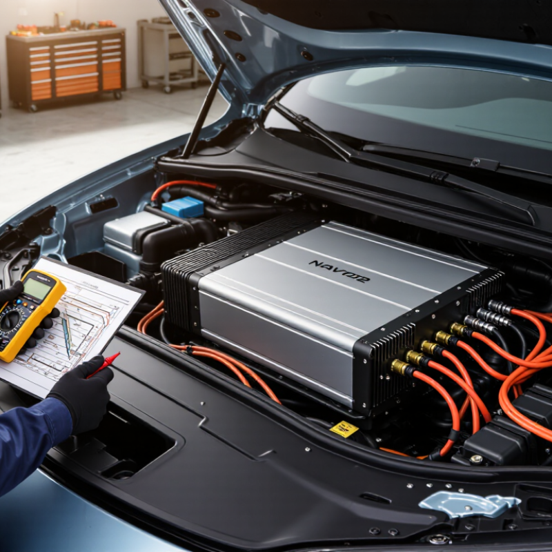
Before buying a TAC2 AC controller, compare its rated voltage with the battery pack’s nominal voltage. Check the battery label and the cart’s service documentation; do not guess from charger output. A mismatch can prevent proper operation or damage components. Small detail, big consequences. Also confirm whether the published rating refers to nominal or maximum voltage, since those figures are not interchangeable.
Tip: Check current ratings against the motor data, not just the cart’s appearance. Record the motor’s specified current and the controller’s continuous and peak limits. A brief peak rating does not mean the controller can handle that load continuously. If the motor label is worn or missing, pause and seek reliable service information rather than estimating.
Then review the cart’s wiring, connectors, and battery configuration. For example, note the number of batteries and their individual voltage before calculating pack voltage. Confirm that the controller supports the cart’s actual setup and intended operating load. These checks can feel tedious. They are still worth doing. Specifications may vary by configuration, so verify the exact controller documentation before ordering; a neat-looking match on paper can hide one overlooked rating.
Illustrative example of comparing a cart’s battery and motor ratings with its controller.
In this example, a 48 V controller matches a 48 V battery, while its 300 A current rating is 120% of a motor’s 250 A rated current. These sample values are for illustration only; verify the cart and component manufacturers’ specifications before choosing a controller.
When comparing an AC controller, read its continuous and peak current ratings side by side in the datasheet. Continuous current describes what the controller can handle during sustained operation under stated conditions. Peak current usually applies only for a limited interval. Check how long that interval lasts, and whether the rating depends on temperature or operating voltage. Numbers need context.
For example, a cart climbing a long ramp may demand steady current for far longer than a brief launch. A controller’s peak figure alone cannot show whether it will manage that climb. Look for footnotes about ambient temperature, cooling, and duty cycle. These details can change the practical rating. If the datasheet lists a peak value without a clear duration, pause and ask the supplier for clarification rather than treating it as a continuous rating.
Match the continuous rating to the vehicle’s expected load, then confirm that short bursts remain within the stated peak limit. Leave room for hot days, heavy cargo, and restricted airflow around the controller. A tidy comparison table helps: record each current value, its duration, and the conditions attached to it. I might miss a footnote on a first pass; reviewing the document again is worthwhile. Compare like with like, not just the largest number on the page.
| Tip | What to Compare | How to Read the Datasheet | Buying Check |
|---|---|---|---|
| 1. Match the continuous current | The application’s sustained current versus the controller’s continuous-current rating. | Find the continuous rating and note the stated operating conditions. It is the rating relevant to current carried over an extended period under those conditions. | Confirm the application’s sustained current does not exceed the applicable continuous rating. |
| 2. Treat peak current separately | Peak current, permitted pulse duration, and repetition or duty-cycle limits. | A peak rating applies only within the datasheet’s specified time and operating limits; it is not a substitute for the continuous rating. | Check that startup, acceleration, or other short-duration demand fits both the peak value and its allowed duration. |
| 3. Verify the test conditions | Ambient temperature, cooling method, mounting, and airflow associated with each rating. | Current capability can depend on thermal conditions and installation. Read footnotes, graphs, and derating tables alongside headline ratings. | Use the rating that matches the intended enclosure and cooling arrangement, not an unrelated best-case condition. |
| 4. Check the electrical system limits | Controller current ratings together with the system voltage and supply limits. | Confirm that the stated current ratings apply at the intended voltage and that the controller’s voltage limits suit the system. | Compare the actual supply range and load requirements with the datasheet’s limits and conditions. |
| 5. Account for the load’s operating profile | Normal running current, transient demand, and how often transients occur. | A single peak value does not describe repeated or prolonged overloads. Check any pulse, thermal, or duty-cycle guidance provided. | Use the expected operating cycle to assess both sustained heating and short-term demand. |
| 6. Review protection and wiring requirements | Specified fusing or circuit protection, conductor requirements, and connection limits. | The controller’s current rating does not by itself determine safe wiring or overcurrent protection. Follow the installation and safety instructions. | Confirm the complete installation—including conductors and protection—meets applicable instructions and local requirements. |
| 7. Confirm the exact datasheet revision | Model identification, document revision, and any listed configuration-specific limits. | Ratings and conditions must be checked against the datasheet for the exact controller configuration being considered. | Record the applicable continuous and peak ratings, their conditions, and the datasheet revision before purchase. |
Before buying an AC controller, match its requirements to the vehicle’s original equipment specifications. Confirm the motor type, rated voltage, and current range using the motor label or service documentation. A controller that appears suitable may still use a different motor configuration. Check carefully. Do not rely on a similar-looking vehicle or an online listing alone; small model-year changes can affect compatibility.
Tips: Compare the controller’s voltage and current limits with the motor’s stated ratings. Check cable gauge, insulation condition, and terminal size against the OEM requirements. Verify connector shape, pin positions, and wiring functions with a diagram. Close enough is not enough. Photograph existing connections before removal, but treat photos as a reference, not proof of pin function.
Inspect the harness for heat marks, corrosion, loose pins, or repaired sections. These details can point to a problem that a new controller will not fix. It is tempting to assume matching plugs mean matching wiring; that assumption can be costly. If specifications conflict or are missing, pause and ask a qualified technician to confirm the system before purchase. Keep the documentation and part details together for a more reliable comparison.
When evaluating an AC controller, treat thermal limits and ingress protection as separate checks. Read the datasheet for its operating-temperature range, maximum current, and any derating guidance. These values may change with ambient heat, enclosure size, mounting orientation, and airflow. A controller that handles a load in open air may require reduced current inside a warm cabinet. Check the actual conditions. Measure temperature near the controller after sustained operation, rather than relying only on the room temperature. Keep heat-sink surfaces clear and follow the specified mounting clearances. I would not assume a metal panel alone can remove enough heat.
IEC 60529 IP ratings describe protection against solid objects and water, not heat. The first numeral indicates solid-object protection; the second indicates water protection. Check the exact rating in the datasheet, then confirm it applies to the assembled installation, including covers, connectors, and cable glands. A rated enclosure can lose protection if a gland is poorly fitted. Small detail, big consequence. Also, an IP rating does not establish resistance to condensation, corrosion, or vibration. Match the rating to the real exposure, and verify installation instructions before choosing the controller. Mistakes happen when the label is treated as a complete environmental guarantee.
When evaluating an AC controller, test regenerative braking on a familiar slope, not just on a showroom floor. The deceleration should feel smooth and predictable when the accelerator is released. Confirm that regeneration can be adjusted for the vehicle’s weight, tire size, and battery type. Ask how the system behaves when the battery is nearly full, since limited charge acceptance can reduce braking effect. Small details matter.
Diagnostics should show useful fault codes, controller temperature, and key operating readings—not merely a warning light. The U.S. Department of Energy’s 2014 Improving Motor and Drive System Performance sourcebook reports that motor-driven systems use about 54% of U.S. manufacturing electricity. That broad figure is not a vehicle-efficiency claim, but it reinforces why monitoring drive performance matters. Ask whether service staff can explain fault logs and provide troubleshooting steps before purchase.
Read the warranty carefully. Check its term, covered components, and exclusions for wiring, water exposure, or incorrect setup. Confirm who handles claims and whether replacement parts are readily available. Installation support should include a clear wiring diagram, compatible connectors, and help checking throttle calibration and safety interlocks. Ask about technician support after installation, too. I would not assume a neat manual means an easy fit; compare the instructions with your vehicle’s actual wiring before ordering.
Compare the controller’s rated voltage with the battery pack’s nominal voltage. Check the battery label and service documents. Don’t guess from charger output.
Note each battery’s voltage and the number of batteries. Confirm the cart’s actual configuration. Small detail, big consequences.
Check both ratings against the motor’s specifications. A brief peak rating does not mean the controller can handle that load continuously.
Check motor type, rated voltage, and current range using its label or service records. Similar-looking carts may differ by model year.
No. Check connector shape, pin positions, and wiring functions against a diagram. Photograph existing connections, but don’t treat photos as proof.
Look for heat marks, corrosion, loose pins, and repaired sections. A new controller may not fix these problems.
Read its operating-temperature range, current limits, and derating guidance. Consider airflow, mounting position, and enclosure heat. Measure near the controller after sustained operation.
Under IEC 60529, its numerals describe protection from solid objects and water. It does not establish resistance to heat, condensation, corrosion, or vibration.
Pause if ratings are missing or conflict. Ask a qualified technician to verify the setup. I’d double-check, even when the parts seem to match.
Choosing a Navitas TAC2 AC Controller starts with confirming that its rated voltage and current match the cart’s battery and motor specifications. Compare both continuous and peak current ratings with the controller datasheet, since they describe different operating demands. Check that the motor, cables, and connectors are compatible with the equipment’s original specifications, and make sure the installation can handle the controller’s thermal limits and operating environment. When reviewing ingress protection, use the IEC 60529 IP rating to understand the level of protection against dust and water.
Also consider practical features and ownership support. Review how regenerative braking works with the cart, whether the controller provides useful diagnostic information, and what warranty coverage is offered. Clear installation guidance and responsive technical support can help simplify setup and troubleshooting. By checking these details before purchase, buyers can make a more informed choice and improve the likelihood that the controller will suit the cart’s requirements.